Gunge Release Mechanisms & Gunge Tanks
Over the years of running activities using gunge, I have used a number of different release mechanisms.
The most important thing to remember when putting a release mechanism together is that gunge is more viscous than water, sometimes excessively so, which means that something designed to work with water won’t necessarily work with gunge. In particular the more bends and small constrictions, the worse it will be- therefore something like a toilet cistern really won’t work at all!
Hole in the bucket
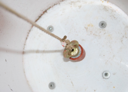
The simplest mechanism I have used is to drill a hole in the base of a bucket, approx 25mm diameter, and ensure the edge is well cleaned up (I have a 1” metal punch that works very well). The hole is plugged using a rubber bung (Demijohn bung intended for home wine making), which has a hole of about 5/6mm bored through it. An eyebolt with a couple of large washers is threaded through so that the eye is at the larger end of the bung. A length of cord can then be tied to the bung to allow it to be pulled out remotely.
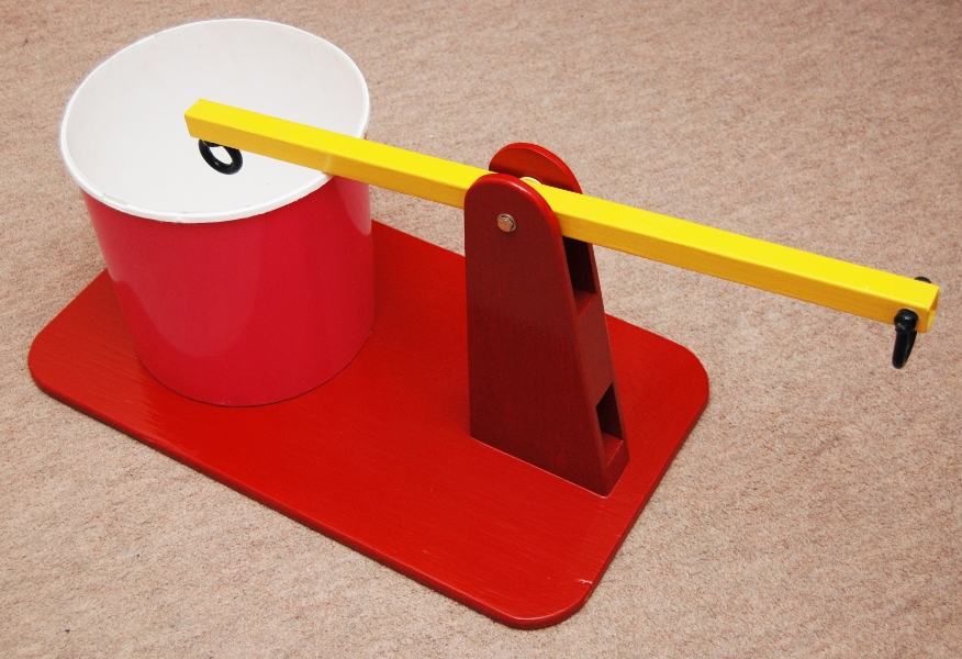
The times I have used this system, the bucket was screwed through the bottom to a piece of plywood, with the hole in the bas lined up with a large hole through the timber. Silicone (bog & bath sealant), and washers were used to make sure the bucket didn’t leak where the screws passed through. A second piece of ply was attached to the base, vertically next to the bucket. To this is attached a hinged batten of timber, with a hole drilled in each end. One hole is arranged to be vertically above the hole in the bucket, and is connected to the other end of the cord to the bung. The hole in the other end of the batten can have another cord attached to enable the mechanism to be released from a distance (or below).
To use, simply put bung in the hole, fill bucket, and pull cord to release. It will need securing reasonably firmly to ensure it doesn’t move unexpectedly when the cord is pulled.
Down the Plughole
A variation on this theme is to use a kitchen sink
mechanism. I used the plug hole assembly from an old kitchen sink to
good
effect in the gunge tank shown below. This was simply removed from the
sink and
fitted to the bottom of a bucket, which was in turn mounted similarly
to the
previous type.
This particular type of plughole had a cable release which was operated by twisting a knob. This was put behind the tank, so could be released by a hidden stage-hand. It could easily have been extended by using a bicycle brake cable.
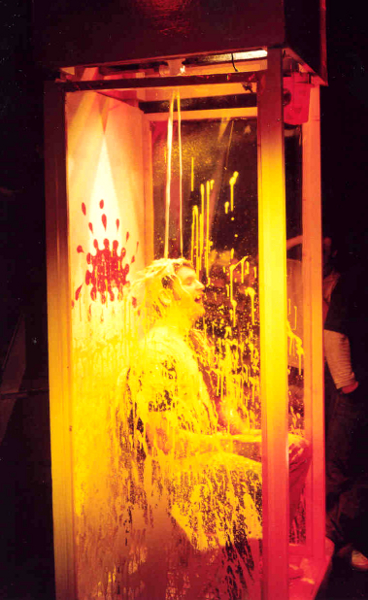
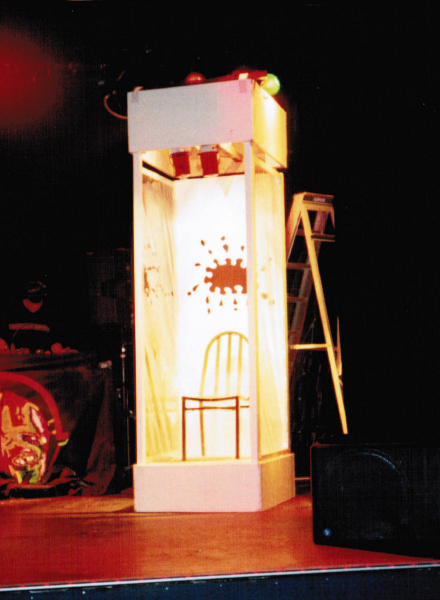
The Gunge tank In use
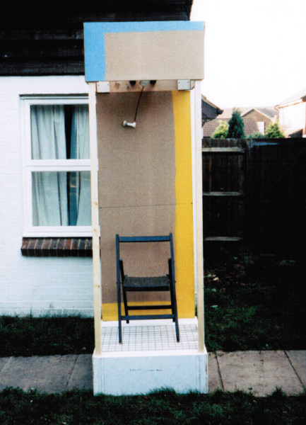
The Tank in Build and Set up before Use
Over the top tank
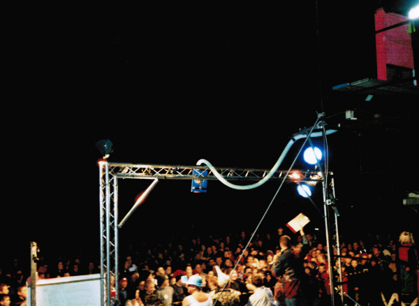
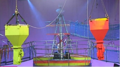
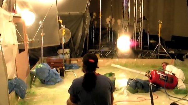
Travelling Overhead gunge tank in use
The final mechanism that I’ve used was a very over the top system, which was spectacular, but not without its challenges. The system was used for the finale of a large ‘It’s a knockout’ style competition at a Scout camp, involving approximately 600 kids. The rig was set up on a stage and consisted of a number of main parts.
Tank- This was a wooden construction about 100mm deep, but about 80cm square, with a clear (acrylic front) and mounted on top of a scaffolding tower. The gunge could therefore be seen clearly by the audience, and was dyed with fluorescent colouring to make it stand out in the UV floodlighting we had rigged (All the other main parts were also painted with UV reactive theatrical paint to achieve the desired glowing effect).
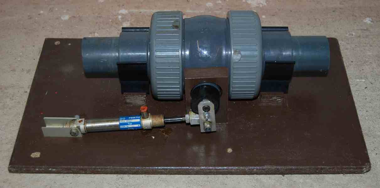
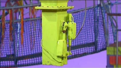
The outlet of the tank was a 2” bore pipe, taken through suction hose to a large 2” bore plastic ball valve. This was actuated by a pneumatic cylinder.
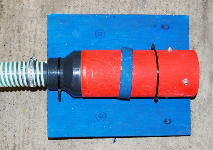
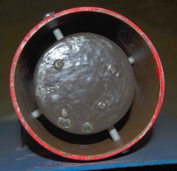
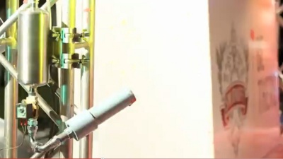
Out of the valve, a second pipe led to the ‘gunge head’, which was mounted on a moveable trolley on a track, which was in turn rigged to a 3m high lighting truss (Tri-lite). The head itself consisted of a 2” to 4” solvent weld adaptor with a wooden plug mounted in the centre. The diameter of the plug was chosen so that the area the gunge would flow through was the same as the 2” bore pipe. This made a continuous, hollow 4” stream come out of the head for a greater effect. The head could be moved along the track to over the top of each of four Scout leaders sat on stage by s couple of pulleys and a length of cord.
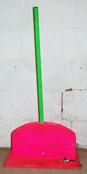
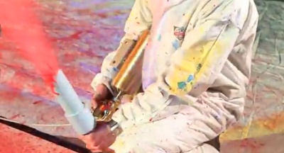
The release was triggered by a large handle at the end of the game. The handle consisted of a piece of square steel tube (an old table leg) pivoting between two cheek pieces of ply, and actuating a pneumatic cylinder this was connected to the valve assembly and water used as a hydraulic fluid. Again this was all painted brightly.
The vast majority of this rig was made from second-hand or scrap parts, except the truss and lighting which were borrowed.
The rig worked well, once we had thinned the gunge down- it needed to be quite watery to flow at a reasonable rate. The activity was popular, and it had the desired effect.
Other Options
There are a number of other possible release mechanisms that can be
used, some more suitable than others. In general, as gunge is viscous,
and may also be lumpy, the best mechanisms will not contain any
obstructions or bends to impede the flow. Lengths of pipe should be
avoided if possible and the bore through the mechanism should also be
kept as large as possible. This rules out some of the more easily
available electric valves as they have a convoluted and narrow fluid
path. For best flexibility, if restriction of the flow is needed to
achieve a specific effect, it is probably best to achieve
this by fixing a nozzle after the mechanism.
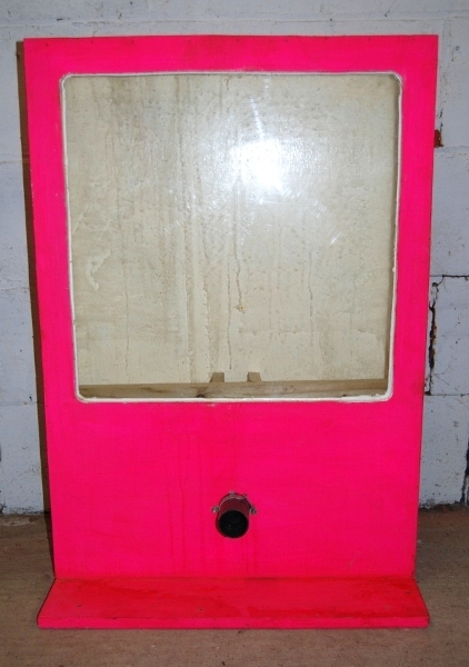
Butterfly
Valves
This operates by a simple ¼ turn and is compact with little impact on
the flow of the valve. These are not widely available outside of
industrial suppliers and are expensive- the photo is of an unused one
salvaged from a scrapyard. As they are intended for industrial use,
they are very robust. Mounting is often by a flange arrangement.
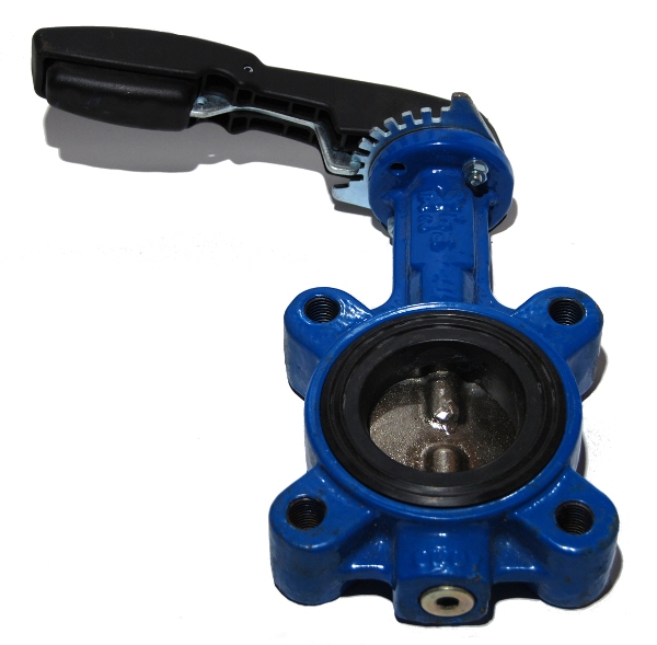
Typical
Butterfly Valve
Ball
Valves
Also operates by a simple ¼ turn, but are generally quite bulky (length
in particular). These are widely available in common plumbing sizes
(15/ 22mm etc), and can be obtained in plastic (PVC/ABS) or metal. The
smaller sizes are unlikely to be able to give sufficient flow for most
uses. Larger bore valves tend to be expensive but can be obtained from
pond/ swimming pool suppliers as well as industrial suppliers.
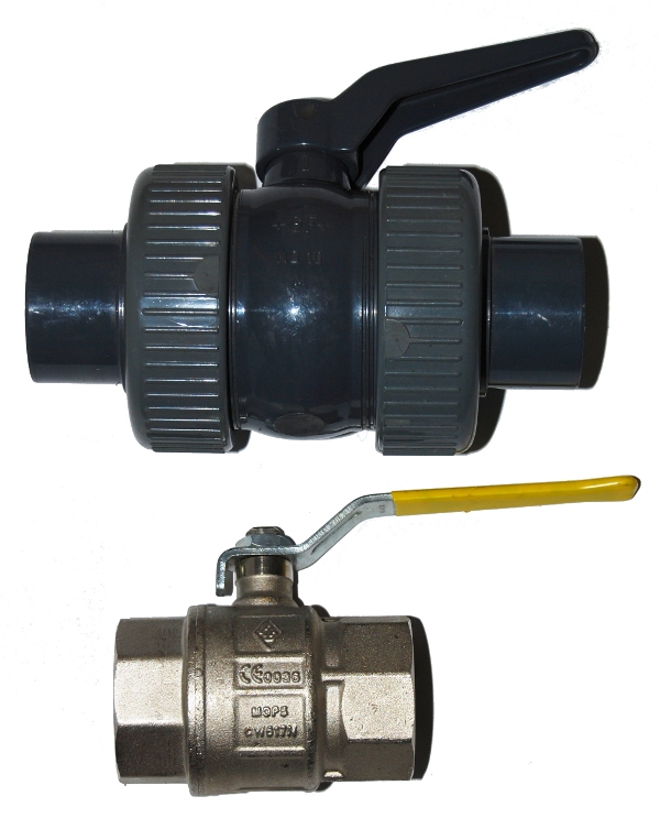
Plastic and Metal Ball
Valves- Identical Bore
Slide
valves
These consist of a simple flat plate that moves in the fluid path. They
are compact, but importantly are available in large bores, cheaply.
They can be obtained from caravan/ RV suppliers as well as pond/
swimming pool suppliers. These may be the best all-round option.
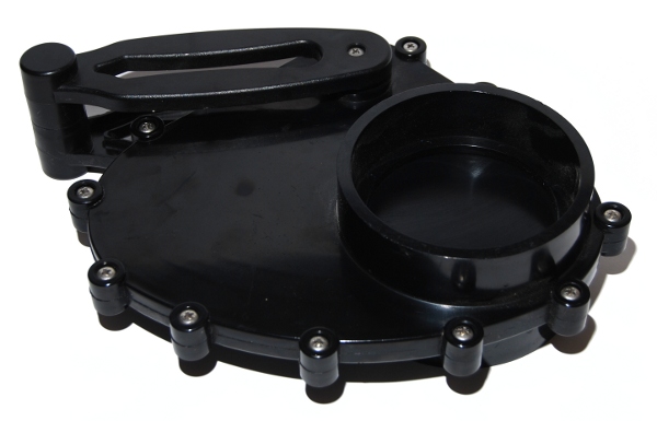
Rotary
Slide Valve
Flush
Valves
There are a number of types of toilet cistern flush valve- some more
suited to use with goo than others, but will not be easy to clean even
if you can find one suitable otherwise. I would avoid these.
Actuation
All of the valves described are normally sold with some kind of handle/
actuator to allow them to be opened and closed, however these may not
suit your needs and another remote form of actuation may be needed. In
the case of industrial valves actuators may be available, although many
are very expensive. For industrial systems they will commonly operate
on air or 24V electrical supply. The only common actuator found on
domestic valves is a mains powered three way actuator used in central
heating systems, however I would strongly recommend not using this type
of part to ensure parts are safe.
Cars contain a number of parts that are eminently suitable for actuating valves remotely- possible parts include windscreen wiper motors and electric window winders, headlight levelling motors etc More suited are central locking actuators and some under-bonnet actuators (Heating flap controls etc). Control circuitry may be required to drive some of these actuators so it would be worth checking if this is the case before obtaining a part. Likewise many automotive parts have very specific connector requirements, so it would be wise to salvage or obtain these at the same time as the actuator if at all possible.
Other possibilities include linear and rotary pneumatic cylinders, large model servo motors and linear actuators. The simplest method of bits of string or levers may often be the most appropriate technique.
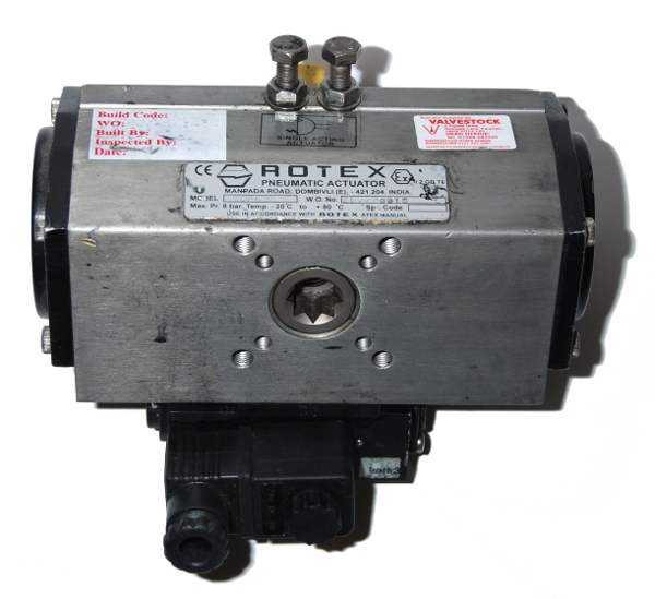
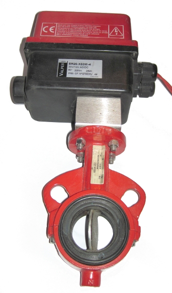
Pneumatic
Rotary Valve Actuator & Motorised butterfly valve
It is almost certain that unless a commercial valve actuator is used, additional brackets will be needed.
Commercial remote actuators for some
of the slide valves are possible, but are not particularly widely
available. A typical example is at the top of this page;
http://www.valterra.com/RV/oemmenu-main.htm
If sourcing valves, care needs to be taken with used parts- many of the valves you will be interested in have potential to have come from sources using chemicals. I would therefore be very wary to ensure that only unused parts or those used with clean water or food products are selected to avoid any chance of exposing yourself to harmful chemicals.
Pyrotechnics
Pyrotechnics have often been used in film and television
applications to act as releases for effects as they are quicker and easier to
rig for one-off remote releases than many alternative methods, such as servos,
solenoids and pneumatics.
I have been unable to find any definitive references to
pyrotechnic release of gunge and slime, but it is highly likely that it has been
used in limited cases. A notable possibility is ‘Pump it Up’, an ITV show aired
in 1999/ 2000 that had around 8 tanks rigged high above an inflatable
set.
There are many ways in which pyrotechnics can be used to effect a release, the simplest probably being taping an electric match/ pyro-fuse to a balloon, although personal experimentation of this type of method hasn’t yet proved fruitful. Other simple methods include using cords or fuse to be broken by the firing of an electric match/ pyro-fuse.
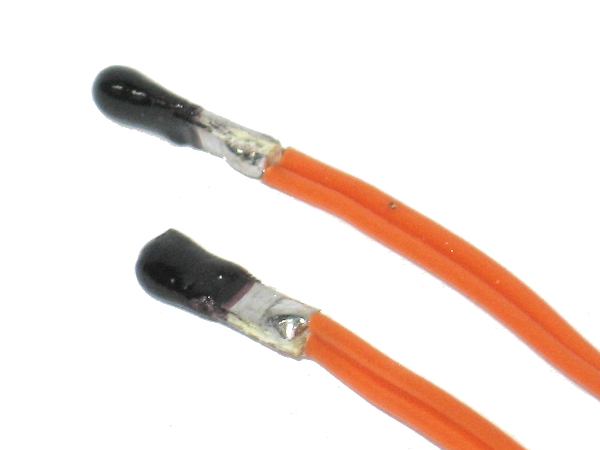
Electric Matches
TV Shows
Many
mechanisms have been used for releasing gunge in television shows using
it- notably twister used a mechanical actauted pair of drop tanks-
below are a couple of screen grabs. Actuation look like it is by
electrical linear actuators.