


Compressed Air Foamer in Action
In recent years the idea of compressed air foam systems (CAFS) have been catching on with fire services around the world, although their use is still not widespread. These systems have significant advantages over other types of fire fighting foam, in particular the distance the foam will project from the nozzle, the small quantity of water required to fight the fire and the ‘clingyness’ of the foam produced. All of these are distinct advantages for the sort of activities that we make use of foam for, so it set me thinking.
CAFS works by injecting a supply of air into the flow of fluid where it exits the pump. This travels along the pipe entrained in the fluid, mixed by the roughness of the pipe. It then expands at the nozzle to form a foam. Expansion ratios of 20:1 to 30:1 are typical, forming a very dense foam with small bubbles, reminiscent of shaving foam.
This project started coming together when I found a standard foam fire extinguisher in the local scrapyard. Many modern extinguishers make use of a Schrader valve to pressurise them making recharging them with a footpump or compressor really easy (compared to older styles that use a small cylinder of carbon dioxide). This style of extinguisher are getting easier to find and lend themselves well to experimenting.
To prove the CAFS concept, I first emptied and cleaned the extinguisher and then re-filled with water and bubble bath. When let off, foam was produced, but was somewhat disappointing- much like a standard extinguisher (as would be expected!). The next stage was to drill a small hole in the dip tube close to where it exits the extinguisher and to remove the foam nozzle from the hose. The results of this were promising, although short lived. A good dense foam was produced, but the pressure dropped very rapidly in the cylinder. It wasn’t giving a burst of much longer than a few seconds. This did prove however that the principal was sound. So I set about making a better system.
Before I go into the description of how I constructed a fully working unit, I shall cover the safety bit:
This unit was built using suitably rated industrial components, it is unlikely you will have access to identical components- select your parts carefully. Systems using compressed air are potentially very dangerous if mishandled, therefore this is not a project suitable for someone new to compressed air projects- please read up, and build up your experience on simpler projects first.
The unit is mounted on a piece of aluminium sheet, folded for about 40mm at the edges to form a cradle. A small piece of angle is fixed at one end to allow a handle to be attached. At the other end of the cradle, two pieces of angle are fitted at the other end to create a base for it to sit on.
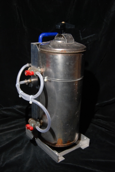
The fluid reservoir is a stainless steel keg that had been used for a water softener system. Simlar units are used for dispensing post mix in pubs and simialar places, commonly known as Soda Kegs. This particular one is an unidentified brand, but similar to a Cornelius ‘Corny’ Keg:
http://en.wikipedia.org/wiki/Cornelius_kegs
The keg is attached to the frame using a couple of giant stainless worm drive clamps salvaged from the scrapyard.
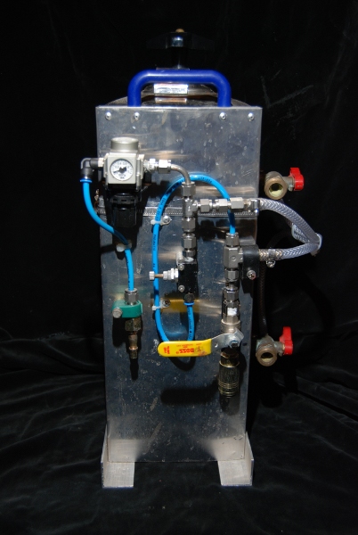
All of the pipework, valves, regulators etc were parts I already had in stock, mostly found in the local scrapyard, and in some cases unused parts. Sorting out how to connect the hotch-potch of parts together did take some time, but was worth it because of the savings made. If you were to start from scratch with new parts, this would be much easier as you wouldn’t have to take account of loads of different thread sizes and sexes.
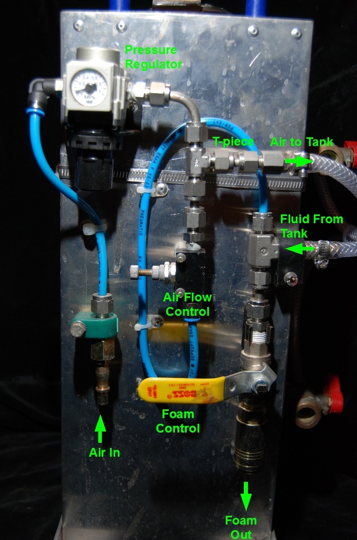
The main air supply comes through a PCL male fitting (Air tool connector).
From the PCL connector, the air supply passes through a regulator. This enables the air to be held at a constant known pressure, and hence give a consistent flow at a known pressure to the foam fluid exiting the tank. This is important in making a consistent foam. Following the regulator there is a tee, one leg going to the feed port on the soda keg. From the other leg of the tee, air is fed through a flow regulator into the water stream. The water comes from the dip tube in the tank and is mixed with the air flow in another tee piece. The output of the tee piece is then fed through a ball valve, and a second PCL fitting, this time a female one.
In practice this incarnation was reached after a number of only partially successful attempts. The original unit had two regulators and one way valves- one to control the pressure in the tank, and the other the feed into the water flow. This however caused the system to pulse heavily, and didn’t give the control over the output I had hoped. The simpler set-up described works better.
The other area that seems to have a somewhat disproportionate affect on the output is the hose size and nozzle. The setup as shown works well, but I had hoped to have a trigger nozzle to turn the output on and off easily. Attaching a air blowgun allowed the control, but completely stopped it foaming. I’m sure that there must be a way to make this work, but haven’t yet worked out the optimum.
A commercial version of this type of product would be:
Something like this unit is used in the New Zealand kids saturday morning show "What Now" in their game "Foam a Friend". Less obvious uses are in many films and television programmes to create snow effects.
Other Foam Machines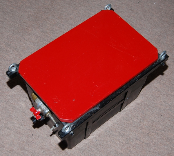
This foam machine
is built from a load of mainly scrap plumbing parts. It is the mark IV
version of the machine- the previous three working on a different
principal. All were built to make large quantities of foam for Scout
'It's a Knockout' type games.
The unit works semi automatically. A water feed hose is connected to
ball-cock to keep it topped up. Air is blown from a small compressor
through small holes in the copper pipe, making the foam, which exits
through the hole in the front. A wooden lid covers the top, and sits in
a frame so it can be suspended. Just needs a top-up
of bubble bath periodically.
There are commercial machines available, however these either have a low output (Antari machine at approx £200 from Maplins) or are very expensive if of the type used in night clubs (£3000 upwards to purchase or £400 upwards to hire). I therefore have built several, working on a couple of principles.
Foam can be defined in terms of expansion ratio (a term adopted from firefighting). A medium expansion foam is one where the air to liquid ratio is around 10:1. This produces a very 'wet' foam that is widely used for firefighting, but is difficult to make, and collapses quickly. Special detergents are also used. Equipment to produce this foam also requires high water pressures. It is for these reasons that I will not cover this in more detail.
High expansion foams are those at which the expansion ratio is between 100:1 and 1000:1. These types are much easier to produce, and will resemble the foam on your bath! There are two ways of producing this type of foam.
One is to bubble air through a detergent solution as described above, the other uses a gauze inflated by the use of an air supply (fan) which is in turn wetted by a detergent solution. The air passing through the gauze therefore produces bubbles at each hole, much like a kids bubble blower, which then conglomerate into one mass. If the mass of foam is discharged by gravity, then the device is known as a foam generator, however if the foam is projected by being picked up by a secondary airflow, or by restricting the foam outlet of the generator, a foam cannon is formed.
The first 2 machines I constructed, were very simple, made from car parts. Indeed the prototype was made from a cardboard box! (unfortunately I have no photos of this). Such machines are capable of producing approximately 1/2 cubic metre (500 litres) of foam a minute. The machines consist of a wooden box, approximately 18" to 2ft long.
At one end of the box is mounted a car radiator fan, set to blow through the box. On both ends of the box are holes, the same diameter as the fan. Both holes are covered with a 1/4" square galvanised mesh. The inside end of the box opposite to the fan, over the hole is covered in a fabric mesh/ gauze. The gauze should have holes no larger than about 1/8", but should be made of thick thread that will hold a reasonable amount of fluid (ie not net curtain material).
A windscreen washer pump is mounted inside the unit, with the input taken out on a tube a couple of metres long, with a foot filter mounted.The pump feeds a number of garden micro irrigation nozzles, mounted approximately 8 inches inside the gauze. A degree of trial and error is required to determine the number of nozzles required, their distance from the gauze, and arrangement, so that maximum, and even wetout is acheived. Power is arranged so that it is switched seperately to both the fan and pump, to give a degree of control. The box is painted, sealed and provided with handles.
Coloured Foam

Coloured
foam is not a particularly easy effect to achieve, and the majority of
effects that I have seen using it tend to end up with a fairly light
colour. I decided to try and find a practical way of colouring foam
effectively.
It would be possible to use a liquid dye (food
colouring or similar) to achieve colouring of the foam, however there
are a number of distinct disadvantages to this: concentration of dye to
impart a sufficiently vivid colour would be very high, and in turn by
using a dye at this strength would almost certainly stain a large
proportion of surfaces. In addition as the surface tension and density
of the dyes are different to the detergent solution, there is a
tendency for the dye to drain out of the foam quite rapidly, losing the
effect quickly.
These factors therefore drove me to using a
pigment rather than a dye to colour the foam, and to find a formulation
that would work with this. Previous experimentation with various types
of gunge had given me a reasonable degree of experience with this type
of formulation (for more background on this, see the gunge page on this
site). I therefore chose to use powder paint as the pigment.
The
key disadvantage of the powder paint is that it is particulate so will
either tend to clump, or drop out of suspension if not kept stirred,
either of which would result in loss of colour or more importantly
blockage of pipes or nozzles. Fortunately there is a way of reducing
this effect- using a shear thinning thickener- this is a thickener that
has a high viscosity at rest, but reduces as it is stirred or made to
flow. This means there is a much reduced tendency for the pigment to
drop out whilst standing, but flow is still possible. After some
experimentation I arrived at a mix of 5% (w/w) powder paint in mixed
into hot water and then followed by Xanthan gum at a concentration of
0.25% by (w/w). (Other shear thinning thickeners could be used).
This mix needs to stand for a while (preferably 1hr or more) before use
to ensure the gum is fully hydrated. Just prior to use I then carefully
stirred in 3% (v/v) of baby bubble bath (being careful not to do this
too vigorously!).
Mix prior to use
The
effect seems to be most pronounced when the foam bubbles are small, so
I use my compressed air foamer which gives a really nice effect, as can
be seen in the pictures here.