How to Make a Quality Crimped Joint
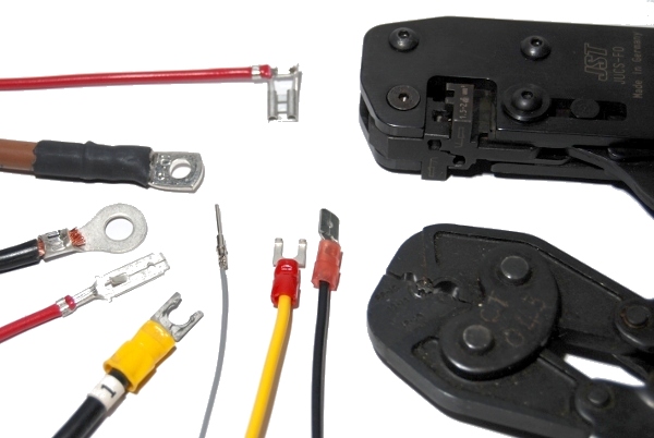 A Range of Finished Crimps With Tools
Whilst
understood well within professional harness makers, the correct
application of crimps is something that doesn’t seem to be as widely
understood in DIY circles with much information available ranging from
not very thorough to out-rightly wrong; One of my friends was once
given the advice by an employee in a car hi-fi shop to hold the crimp
onto the cable with insulating tape and nothing else....... Crimping is
a technique that can produce reliable, long lasting joint, efficiently
and easily with very little training.There
are a vast range of crimps out there in the market- industrial users of
crimps have good access to information from the crimp and tooling
manufacturers so I won’t go into depth on these applications. Instead,
in this Instructable I hope to give some advice on using crimps that
you are likely to encounter in installing accessories or making repairs
to your car, boat or caravan or in projects at home.Much
of this page will focus on materials and tools, so I will split this
down into detail in three main areas and will keep the introduction
materials simple:MaterialsGood quality crimp terminals to suit the applicationStranded wire of a known specification (not solid core)Heatshrink ToolsGood quality wire cuttersCrimp tool to suit the terminals Step 1 Choosing the wireDepending
on your application, you may or may not have a choice on the wire to
use. Firstly do not use solid cored wire, and if you want a reliable
job heavily avoid ‘conduit wire’ (a few largish strands intended for
mains buried in conduit). Specific types of crimps are required to use
this type of wire reliably. The best wire for general use will be one
with many strands.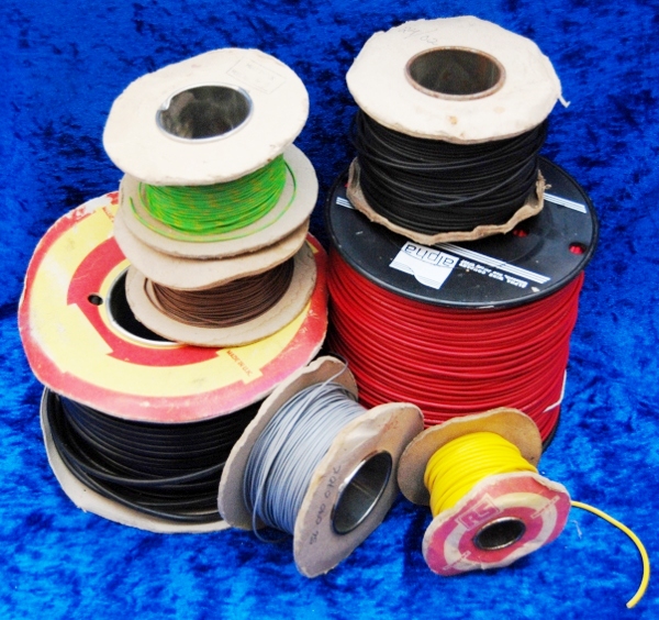 Wire Types
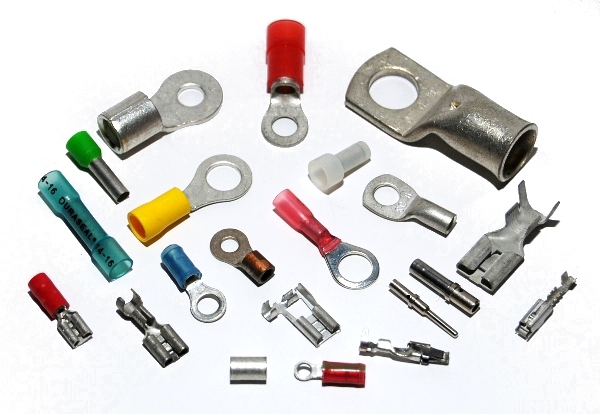 A Range of Possible Crimps
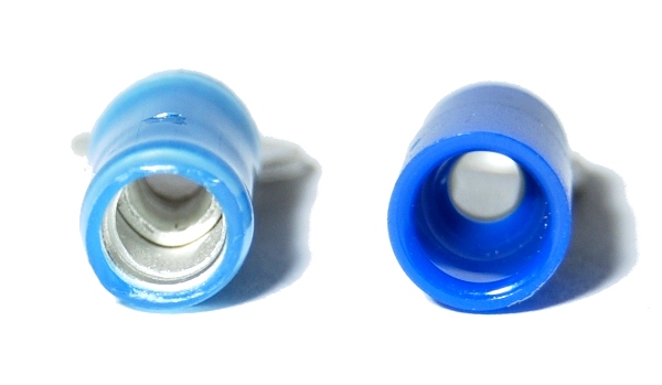 Preinsulated Crimps- (better quality terminal on the left
)
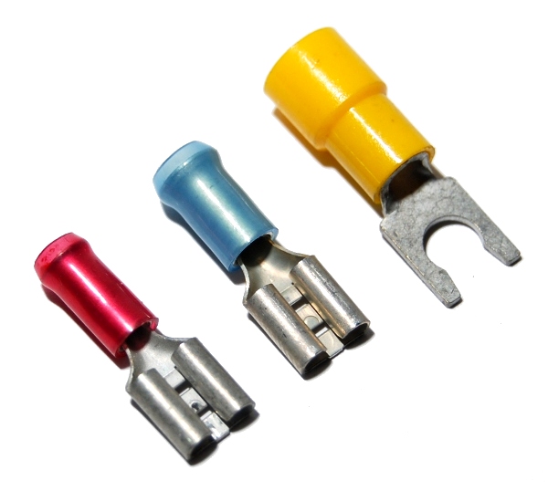 Common Three Sizes of Insulated Crimps
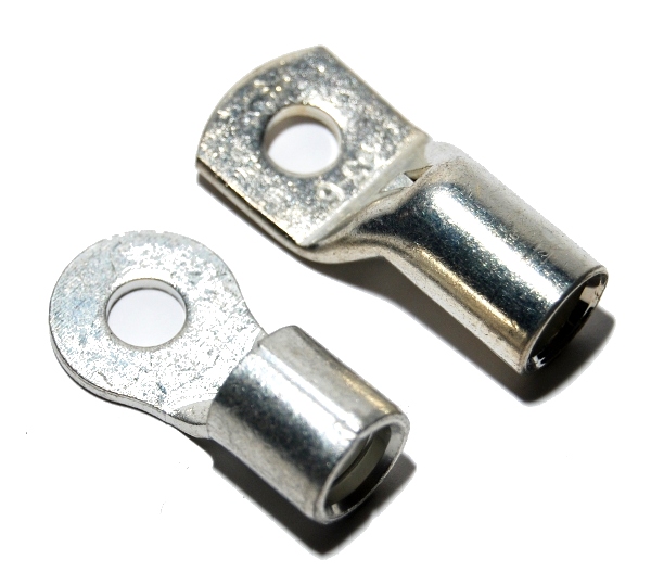 Sheet and Tube Formed Crimps
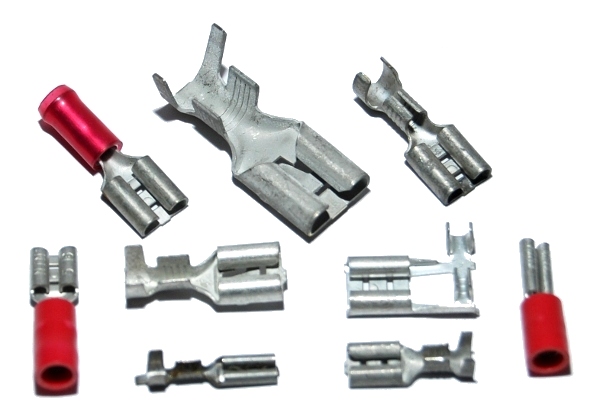 Blade Type Crimps
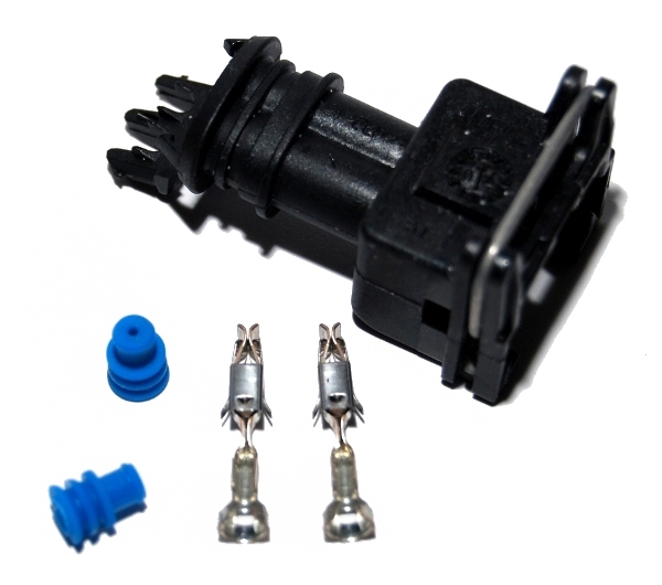 Junior Power Timer Crimp Kit
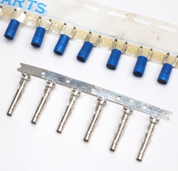 Crimps as Packaged For Volume Production
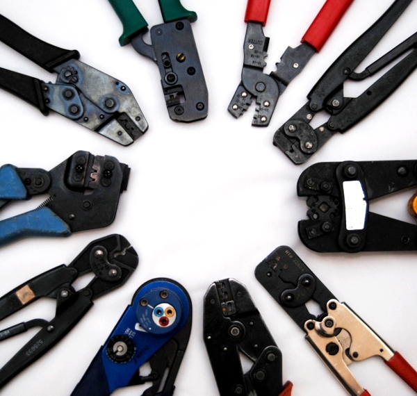 A Wide Range of Crimp Tools
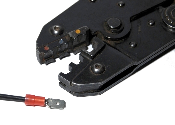
 Wire in Crimp With Tool, and Finished Termination
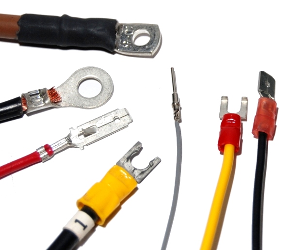 Finished Crimp Terminations
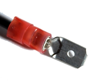
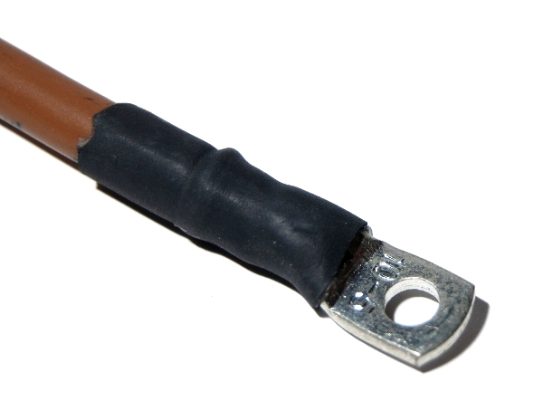 Heatshrink Insulated Terminal
(c) M.Pantrey 2012